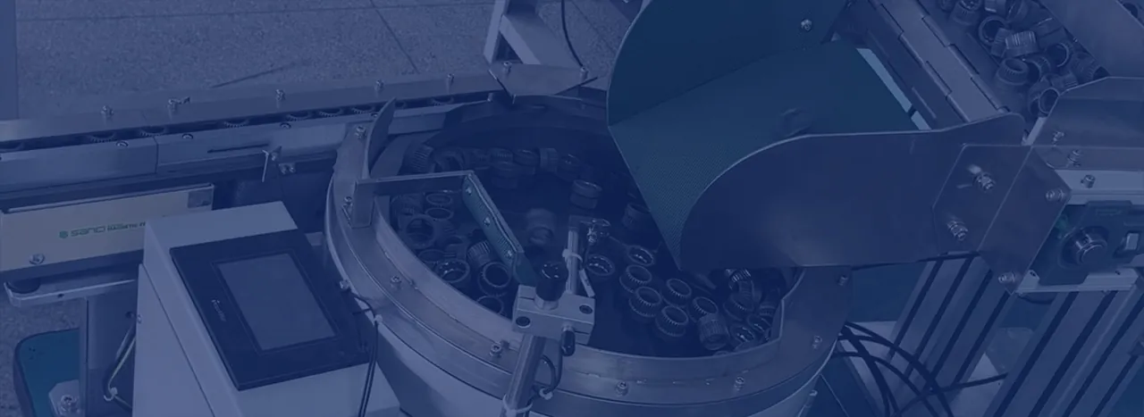
What is bowl feeder tooling?
The bowl creates controlled movement; the tooling creates the orientation result. Tooling uses the component's shape, centre of gravity and stable resting positions to distinguish an acceptable attitude from every incorrect alternative.
A tooling route may include narrowed tracks, profile rails, wipers, height gauges, edge selectors, air jets, optical sensors, reject drops and controlled recirculation. The final design should achieve orientation without creating excessive jams, marking or sensitivity to normal production variation.
How is the tooling route developed?
- Observe bulk behaviour. Identify nesting, tangling, overlap, preferred resting faces and the effect of vibration.
- Define the accepted datum. Agree exactly what the next machine needs at the outlet.
- Use stable features. Select geometry that separates good and incorrect poses with the fewest fragile adjustment points.
- Plan rejects and recirculation. Return parts without damaging them or destabilising the accepted stream.
- Prove the discharge. Test the final track, buffer and escapement with realistic machine demand.
Tooling decisions that affect reliability
| Tooling decision | Engineering check | Risk if missed |
|---|---|---|
| Track width and profile | Can every accepted part travel without wedging? | Intermittent jams or double presentation. |
| Selector and reject point | Does it discriminate across all tolerances and variants? | Good parts rejected or wrong parts passed. |
| Recirculation path | Will repeated contact mark, deform or contaminate the component? | Cosmetic damage and unstable feed. |
| Access and setting control | Can tooling be cleaned and maintained without losing the datum? | Long restarts and uncontrolled adjustments. |
| Discharge interface | Does the track remain stable under back-pressure and stops? | A correct bowl with an unreliable hand-off. |
Tooling for multiple variants
Related variants may use adjustable rails or change parts, but changeover must be repeatable and protected from incorrect settings. If the component family is broad, compare dedicated tooling with robotic flexible feeding before the architecture is fixed.
What should a tooling trial record?
Record the sample set, tooling settings, accepted orientation, reject behaviour, recirculation, sustained output, marking observations and recovery after a jam or full-track stop. That evidence creates a clearer acceptance baseline than a short demonstration video alone.