UK support for component orientation, inspection & presentation projects

Inspect · classify · verify

Machine vision inspection for production components.

Verify that each component is present, correctly oriented and within agreed visible criteria before it enters the next operation.

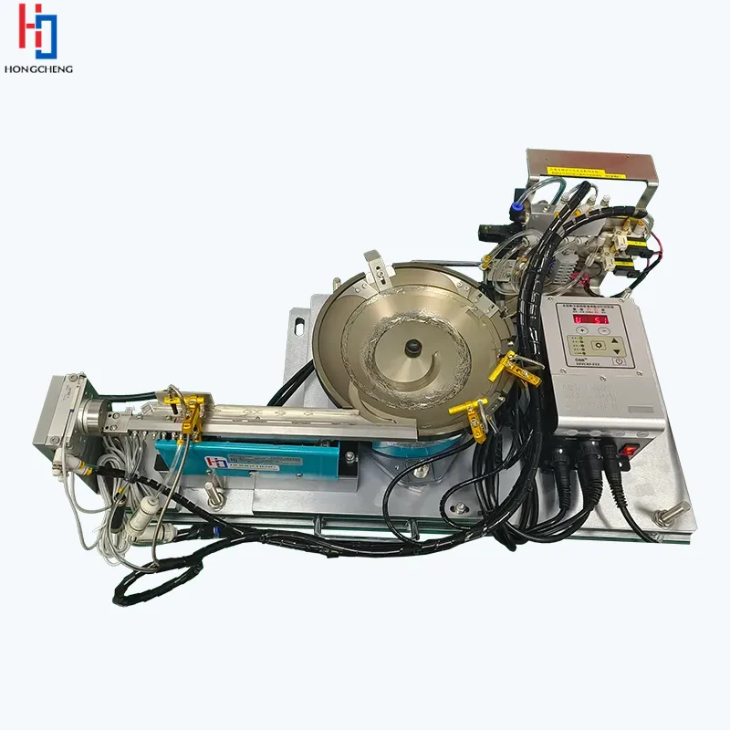
Metal bowl feeder with linear outfeed tooling, wiring and a control unit.
Vision inspection is most reliable when the component presentation, lighting, camera view and reject mechanism are engineered together.
Direct answer

Component vision inspection combines controlled presentation, lighting, optics, image processing and reject logic to make repeatable pass, reject or classification decisions.

Translate a visual judgement into a measurable task.

A request to “check the component” is not yet a vision specification. Each criterion must be visible, repeatable and linked to representative samples. The feature size, contrast, location, motion and normal product variation determine the camera, lens, lighting and presentation method.

Orientation

Pose & direction

Top/bottom, leading feature, rotational position or correct face.

Assembly

Presence & completeness

Holes, inserts, clips, seals, moulded details or fitted components.

Classification

Variant & identity

Geometry, colour, mark, code or visible dimensional features.

Lighting is part of the inspection.

The same feature can appear differently as material, finish or orientation changes. Backlighting can create a clear silhouette, diffuse lighting can reduce glare on mouldings, polarisation may control reflections, and directional light can reveal surface or height detail. Lighting trials should use the actual component range.

Presentation controls false decisions.

A stable view reduces variation that the image tools must tolerate. Components may be inspected on a linear track, in a nest, across a conveyor, on a flexible feeder plate or through several controlled views. If a critical feature is hidden in the first pose, a reorientation or second camera may be needed.

Reject handling must close the loop.

Options include air rejection, gates, diverters, robot removal, controlled recirculation or line stop. Where containment matters, a reject command can be paired with confirmation sensing and a secure reject bin. The system should define what happens after a missed trigger, failed reject or full bin.

RequirementEvidence neededTypical output
Orientation verificationCorrect and incorrect samples in all normal positionsPass, recirculate or reject
Presence checkComplete and known incomplete assembliesPass, reject or line stop
Variant classificationFull format matrix and boundary samplesRoute, count or recipe check
Visible defect detectionDefined defect library and acceptance limitsReject, grade or image record

Validation and image records.

Acceptance can use challenge samples, repeated presentations, worst-case colours and finishes, and an agreed false-accept/false-reject method. Systems may store reject images, statistical samples or every image where the controls, network and retention scope require it.

Practical answers

Common questions

What defects can machine vision detect on components?

Vision can assess features that are visible and sufficiently repeatable under controlled imaging, including orientation, presence, dimensions, colour, print and selected surface defects.

Can AI vision inspect variable cosmetic defects?

Machine-learning tools can help with variable visual patterns, but they still require representative training and validation data, controlled presentation and a clearly defined decision boundary.

Can vision inspect a moving component?

Yes, if the camera trigger, exposure, lighting and transport stability produce a consistent image at the required rate. Some tasks benefit from stopping or nesting the part.

Can inspection images be saved?

Yes. The system can be scoped to retain rejects, statistical samples or every inspection, subject to storage, traceability and network requirements.

Start with the component

Show us the part and the condition your machine needs.

Send photographs or drawings, representative variants, required orientation, target sustained rate and the downstream interface. We will identify the most suitable next engineering step.

What does a component vision inspection system check?

A component vision system can check presence, orientation, visible geometry, colour and markings when the camera, lens, lighting and presentation are designed around a measurable accept or reject condition.

Decide whether a failed view means reorient, reject or stop

Distinguish presentation from component quality

An otherwise acceptable component may arrive upside down or with a critical face hidden. That is a presentation problem; a missing or damaged feature is a different decision. Agree which conditions may return to the feeder and which require contained rejection. Recirculating every failed image can repeatedly return a genuinely defective part, while rejecting every unsuitable pose can discard good components. Build the classification around the actual component and required next operation, with a defined outcome when the image does not support a confident decision.

Use a pose-and-variant challenge matrix

For each approved part variant, list acceptable poses, incorrect poses, ambiguous features and visible defects. Include finish and supplier variation, then mark which camera view supports each decision. Challenge the same component at the permitted extremes of position and angle rather than only in a carefully arranged central pose. Keep setup examples distinguishable from the samples used to assess the agreed result. Record cases where the image cannot separate a wrong variant from the correct component so another feature or method can be considered.

Prove the decision at the receiving process

Follow a part from image trigger to release, reject or recirculation. Challenge an absent trigger, a double part, a delayed result and a receiving machine that stops mid-sequence. Confirm that the result remains associated with the correct component. If a part is recirculated, define how repeated unsuccessful presentation is handled and how it affects accepted output. Count usable presentations and resolved rejects separately from total images processed. This closes the gap between a successful camera demonstration and a feeding system that supports the assembly operation.

Keep a vision decision stable across normal production variation

A component inspection may perform well on a prepared sample set and behave differently after a material change, cleaning or adjustment. Define which production changes should trigger a check of the established inspection.

Retain separate development and check samples

Identify which samples were used while setting up the inspection and which were reserved to assess the final settings. Include normal acceptable variation and representative unacceptable conditions. Repeatedly tuning against the same small set can conceal whether the configuration handles a genuinely different production batch.

Report the two error directions separately

An acceptable component rejected by the system and an unacceptable component passed onward have different consequences. Record both against the agreed sample classifications, together with uncertain views. A single overall accuracy percentage can hide the error that matters most to the assembly process.

Record the optical configuration

Keep the camera, lens, lighting arrangement, exposure settings and mounting references with the inspection revision. Check the established reference conditions after cleaning or an authorised adjustment. A changed image should prompt investigation of presentation and illumination before thresholds are altered to make the result pass.

Control recipe and software changes

Associate the approved component family with the correct inspection configuration and the physical reject sequence. Record why a change was made and which checks were repeated. Preserve a recoverable approved version so a production issue can be investigated without losing the comparison with the previous state.

Review component orientation and inspection

Call 01844 617223Send component details