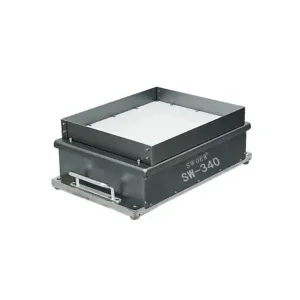
The complete flexible feeding cell.
- Bulk supply meters components onto the presentation plate.
- The platform moves parts to separate, flip and redistribute them.
- Controlled lighting and a camera create a repeatable image.
- Vision software returns one or more valid pick poses.
- A robot and gripper pick and place the component into the process.
The PLC or robot controller coordinates replenishment, image triggers, pick results, redistribution and fault recovery.
What makes a component pickable?
The camera needs a recognisable outline or feature with sufficient contrast, and the gripper needs accessible, stable contact. Overlap, translucency, reflection, flexible geometry and deep nesting can reduce the percentage of usable parts in each image.
Recognisable pose
A visible silhouette or feature across normal colour and finish variation.
Accessible surface
Vacuum, parallel, compliant or application-specific gripping access.
Stable destination
A nest, assembly, conveyor pocket or process datum the robot can reach.
Calculate sustained output, not robot speed.
Throughput includes platform motion, settling, image exposure, processing, robot travel, grip confirmation, placement, redistribution, replenishment and recovery after failed picks. Two robots or multi-pick tooling only help if the plate consistently presents enough valid components.
When flexible feeding merits assessment.
- Several compatible formats need recipe-based changeover.
- Components are delicate, easily marked or difficult to recirculate.
- Mechanical orientation would require complex fixed tooling.
- Robot placement is already part of the assembly process.
- The required part feature is easier to locate visually than mechanically.
When dedicated tooling may be better.
For one stable component at high volume, a bowl or centrifugal feeder may offer a simpler cycle and more compact automation. Flexible feeding should be selected because it resolves variety, handling or geometry—not because it looks more advanced.
Recipe and changeover control.
A new format may require a vision recipe, lighting setting, platform motion recipe, gripper fingers, bulk metering setting and new placement coordinates. The system should confirm that the correct mechanical tooling is fitted before production begins.