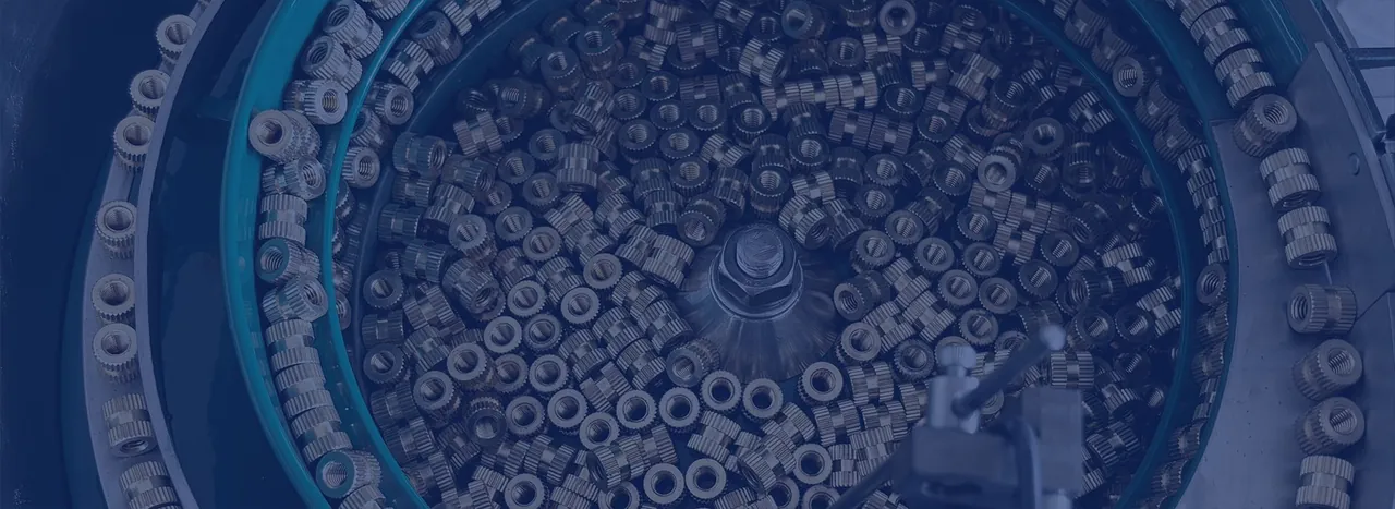
Orientation begins with part behaviour.
Two components with similar dimensions can behave very differently in bulk. Centre of gravity, symmetry, friction, flexibility, nesting, tangling, surface condition and manufacturing variation all affect the method that will produce a stable feed.
We assess the complete route: how components enter the feeder, how they are separated, which features can be used for orientation, how incorrect parts return or recirculate, and how the accepted stream reaches the receiving machine.
Do not specify “parts per minute” alone. Specify accepted parts at the agreed discharge orientation and datum.
Common orientation technologies.
Vibratory bowl feeders
A bowl feeder moves components around a helical track. Tooling uses mechanical features, gravity, air jets, sensors or vision to retain correctly oriented parts and return incorrect ones. It is a strong route for stable, repeatable components and dedicated production.
Centrifugal feeders
A rotating disc or tooling ring moves components to the outside of the feeder and into orientation tooling. Centrifugal systems merit assessment where higher flow and gentle, smooth movement are priorities, provided the part geometry suits the method.
Step feeders
Stepped lifting plates elevate parts from a low-level hopper to a linear discharge. They can reduce noise and part-on-part recirculation for larger, heavier or surface-sensitive components.
Flexible feeders
A controlled presentation surface, camera and robot replace much of the fixed orientation tooling. Flexible feeding can suit compatible variants, delicate parts and geometry that is difficult to orient mechanically.
| Method | Often considered for | Main engineering questions |
|---|---|---|
| Vibratory bowl | Dedicated parts, complex mechanical orientation, compact feed path | Tooling features, recirculation, noise, marking and change parts |
| Centrifugal | High-flow, stable components that tolerate rotary handling | Part stability, tooling circumference, reject return and gentle handling |
| Step feeder | Larger or heavier parts, lower noise and loading height | Step geometry, elevation rate, discharge control and buffer capacity |
| Flexible feeder | Several compatible variants, delicate or hard-to-tool components | Pickable yield, lighting, robot cycle, overlap and recipe control |
Hybrid orientation and verification.
Mechanical orientation can be combined with a final camera or sensor check when one feature cannot be reliably tooled, when variants must be classified, or when the receiving process needs positive confirmation. Rejected parts can be recirculated, diverted to a controlled bin or used to stop the line, depending on the risk.
What the acceptance test should prove.
- Every agreed component variant is handled.
- The sustained accepted output is maintained over the agreed test period.
- Incorrectly oriented parts are rejected or recirculated as specified.
- Normal replenishment, back-pressure and recovery conditions are included.
- The final datum, spacing and handshake suit the receiving process.