UK support for component orientation, inspection & presentation projects

Buffer · release · hand off

Component escapements and controlled presentation.

Deliver one accepted part—or a defined group—in the exact position, spacing and timing required by the receiving machine.

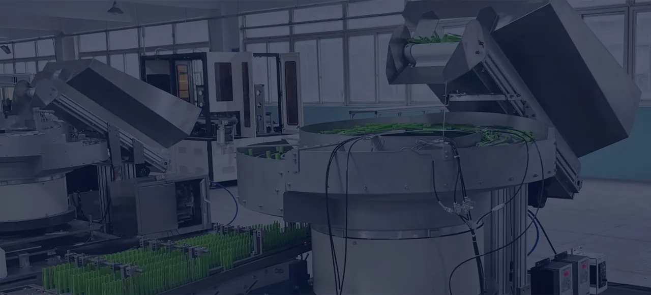
Bowl feeders and hopper elevators with green components on the feeding line.
Linear tracks, sensors and escapements connect the orientation device to the actual cycle of the receiving machine.
Direct answer

Component presentation is the final controlled hand-off that locates, buffers and releases an oriented part to a machine, robot, assembly station or packing process.

The discharge condition is the real specification.

A feeder can orient parts correctly and still fail in production if the final hand-off is unstable. The last section of track, the queue behind the escapement, the part-present sensor and the receiving machine cycle determine whether every component arrives consistently.

Presentation methods.

Linear tracks and buffers

A straight vibratory or driven track transfers oriented parts and provides controlled accumulation. Track geometry, coatings, covers and sensor positions are developed around part stability and acceptable back-pressure.

Escapements and one-part release

An escapement separates the leading part from the queue and releases it on command. Pneumatic, servo or mechanical devices may be used depending on cycle time, force, accuracy and environment.

Nests and datum stations

A nest can establish the final location and support a robot pick, press operation, assembly step or secondary inspection. The nest may include clamps, part-present confirmation or poka-yoke features.

Tubes, chutes and blow feeding

Suitable components can be transferred through gravity chutes or delivery tubes. Air-assisted transfer requires assessment of part stability, impact, noise, contamination and the receiving stop.

Define “ready” as a physical position plus a control state: part located, sensor confirmed and the receiving machine permitted to cycle.

Buffering and line balance.

The feeder should not hunt with every machine cycle. A correctly sized buffer absorbs short interruptions and lets the orientation device run in a stable range. Low-level and high-level sensing control replenishment, feeder output and fault timing.

Control handshakes.

  • Ready-for-part and request-part signals
  • Part-present and part-taken confirmation
  • Buffer low, full and jam states
  • Feeder enable, reset and permissive signals
  • Reject confirmation and reject-bin status
  • Safe stop, guarded access and restart sequence

Robot-ready presentation.

A robot may pick from a fixed nest, a moving conveyor, a flexible feeder plate or a controlled array. The gripper approach, access, datum repeatability, pick confirmation and failed-pick recovery should be considered with the presentation method.

Practical answers

Common questions

What is a component escapement?

An escapement isolates one component—or a defined group—from an accumulated queue and releases it to the receiving process at the required time and position.

Why is a linear buffer needed after a bowl feeder?

A buffer separates short variations in feeder output from the machine cycle and allows the orientation system to run more steadily while maintaining parts ready at the discharge.

Can parts be presented directly to a robot?

Yes. Parts can be located in a fixed nest, picked from a conveyor, or identified on a flexible feeder plate, depending on pose accuracy, rate and gripper access.

What controls signals are normally required?

Typical signals include machine request, feeder ready, part present, part taken, buffer status, faults, reset and safety permissives. The exact handshake is agreed with the line controls.

Start with the component

Show us the part and the condition your machine needs.

Send photographs or drawings, representative variants, required orientation, target sustained rate and the downstream interface. We will identify the most suitable next engineering step.

Specify the feature that makes a part assembly-ready

A component can appear correctly oriented yet remain unsuitable for the next operation. A cylindrical part may stand upright while a slot, keyway or connector feature faces the wrong direction. Describe the feature that the receiving process actually uses, including any rotational position that matters after the part has reached the final nest.

Supply a marked photograph or drawing showing the reference face, leading end and critical feature. State which variations are acceptable and which require rejection or further alignment. If the part is nearly symmetrical, provide samples of the confusing poses. This helps establish whether mechanical tooling can establish the final position directly or whether an additional feature check or orientation stage merits a trial.

Confirm the same requirement with the gripper or fixture designer. The feature used for detection must remain accessible, and the transfer must preserve the accepted pose. In the acceptance record, describe a good hand-off in observable terms so both suppliers judge the same result. This approach is particularly useful for keyed inserts, connector housings and turned parts whose outside shape hides an important assembly direction.

Does an upright component always have the correct orientation?

No. A keyway, slot or other functional feature may still require a defined rotational position.

What drawing best explains a component presentation requirement?

A marked view showing the datum face, leading end, critical feature and allowable final position at the receiving process.

Call 01844 617223Send component details